Super detailed chemical plant flow chart!
Quick answer: For paint and coating topics, formulators usually compare flow, substrate fit, surface quality, and durability together because the same adjustment can improve one property while weakening another.
Flow chart of isomerization device
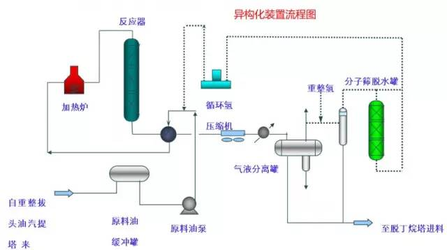
An isomerization unit is similar to an ordinary hydrofinishing unit.
Take butane isomerization as an example (see figure), butane feed is separated from isobutane by de-isobutane tower, and n-butane is mainly at the bottom of the tower, which is mixed with hydrogen and heated into the reactor. The reaction pressure is about 2.1~2.8MPa, temperature 145~205℃, hydrogen, hydrocarbon molar ratio is 0.1~0.5, and air velocity is 3~5h-1.
Flow chart of benzene extraction unit
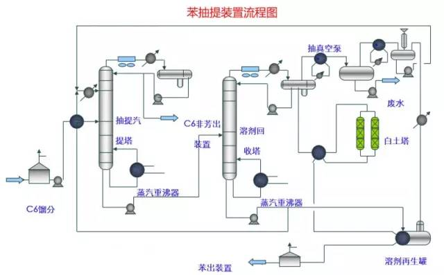
The benzene extraction unit, as a unit for extracting benzene contained in reformed gasoline, mainly includes the following parts: pre-fractionation, extractive distillation, solvent recovery and regeneration, benzene refining and C6 non-aromatic hydrotreating reaction, and fractionation.
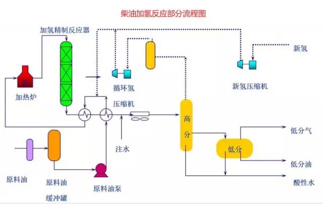
Flow chart of diesel hydrogenation reaction part
Study of polycrystalline type in the development of crystallization process of drugs
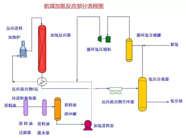
The feedstock oil from the tank area enters the feedstock oil buffer tank, which is sealed with fuel gas, after removing particles larger than 25 micrometers in the feedstock through the feedstock oil filter under the liquid level and flow control of the feedstock oil buffer tank.
The feed oil from the feed oil buffer tank is pressurized by the hydrofeed pump, and then under flow control, after heat exchange through the reaction effluent/feed oil heat exchanger, it is mixed with mixed hydrogen into the reaction effluent/reaction feed heat exchanger, and then heated up to the required reaction temperature by the reaction feed heater, and then enters the hydrofinishing reactor. The reactor is equipped with two catalyst beds and an emergency hydrogen injection facility between the beds.
The reaction effluent from the hydrofinishing reactor is exchanged with the reaction feed, low-minute oil and raw material oil through the reaction effluent/reaction feed heat exchanger, reaction effluent/low-minute oil heat exchanger and reaction effluent/raw material oil heat exchanger, and then it is cooled down to 45℃ through the reaction effluent air cooler and water cooler and then enters into the high-pressure separator. In order to prevent the ammonium salt in the reaction effluent from precipitating out at low temperature, deoxygenated water is injected into the pipeline on the upstream side of the reaction effluent air cooler by means of a water injection pump.
The cooled reaction effluent is separated into oil, gas and water in the high-pressure separator. The high fraction gas (circulating hydrogen) is separated by the circulating hydrogen compressor inlet separator tank, and then enters the circulating hydrogen compressor to boost pressure, and then divided into two ways: one way is used as sharply cooled hydrogen into the reactor; the other way is mixed with the new hydrogen from the new hydrogen compressor, and the mixed hydrogen is mixed with the raw material oil as the reaction feed. Sulfur-containing and ammonia-containing wastewater is discharged from the bottom of the high-pressure separator to the acid water vapor extraction unit for treatment. The high oil phase enters the low pressure separator through a pressure reducing regulator valve under liquid level control, and its flash gas is discharged to the fuel gas network of the plant.
Low-content oil enters the diesel vapor stripping tower through the refined diesel/low-content oil heat exchanger and the reaction effluent/low-content oil heat exchanger after exchanging heat with refined diesel and reaction effluent, respectively. The inlet temperature is controlled by bypass regulation of the reaction effluent/low-minute oil heat exchanger. Fresh hydrogen enters the new hydrogen compressor through the new hydrogen compressor inlet separator tank after separating the liquid and mixing with circulating hydrogen after two-stage pressurization.
Diesel Hydrofractionation Partial Flow Chart
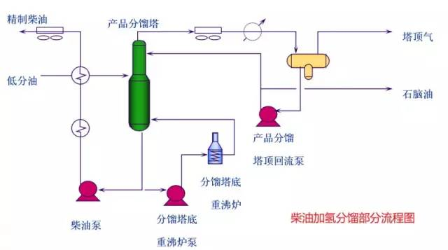
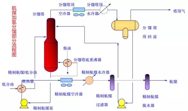
Low-content oil from the reaction section enters the diesel fuel stripping tower through the refined diesel fuel/low-content oil heat exchanger and the reaction effluent/low-content oil heat exchanger to about 275°C. The oil and gas at the bottom of the tower is stripped with 1.0 MPa superheated steam.
The bottom of the tower with 1.0MPa superheated steam vaporization, the top of the tower oil and gas by the top of the vaporization tower air cooler and the top of the vaporization tower after the cooler condensation and cooling to 40 ℃, into the top of the vaporization tower reflux tank for the three-phase separation of gas, oil, water. The flashed gas is discharged to the catalytic device. The oil phase is pressurized by the reflux pump at the top of the stripper tower, and then part of it is used as reflux at the top of the tower, and part of it is used as crude gasoline to go to the catalytic device. Sulfur-containing and ammonia-containing wastewater is sent out of the plant together with the highly fractionated wastewater.
Post-treatment experience in the synthesis process
In order to inhibit the corrosion of hydrogen sulfide on the top pipeline of the tower and the cold exchange equipment, the measure of injecting corrosion inhibitor is adopted in the top pipeline of the tower. Corrosion inhibitor from the corrosion inhibitor tank through the corrosion inhibitor pump into the tower top pipeline.
The bottom of the tower refined diesel fuel by diesel pump pressurization and low oil heat exchange to about 80 ℃, and then into the diesel fuel air cooler cooled to 50 ℃ out of the device.
Partial flow chart of the hydrotreating reaction of aircraft coal
Aircraft coal hydrofractionation part of the flow chart
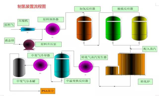
Hydrogen production plant flow chart
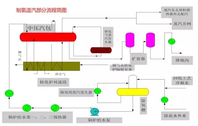
Hydrogen production and steam generation part of the flow diagram
Crystallization Dry 6 || Take a comprehensive look at melt crystallization!
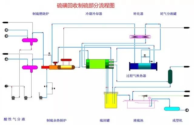
Sulfur Recovery for Sulfur Production Partial Flow Chart
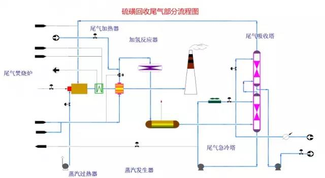
Flow chart of sulfur recovery tail gas section
Solvent regeneration unit flow chart

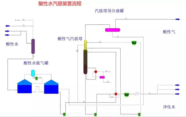
Acid water vapor stripping plant process
A practical checklist for coating formulation decisions
In conventional coating work, technical buyers usually move fastest when they define the film-performance target first and then review rheology, substrate compatibility, additives, and long-term durability as one system instead of isolated tweaks.
- Start from the application scenario: furniture, powder coating, industrial paint, and waterborne systems often reward different formulation priorities.
- Check surface quality and process stability together: leveling, wetting, foam control, and drying often interact strongly.
- Review the film after full cure or drying: adhesion, hardness, weatherability, and color stability usually decide the commercial result.
- Use targeted additive screening: wetting, leveling, defoaming, and wear-resistance additives work best when the defect is clearly defined.
Recommended product references
- CHLUMIAF 094: A balanced defoamer reference for waterborne coatings and many general foam-control screens.
- CHLUMIAF 3062: Useful when printing-ink and UV-ink compatibility matter in the defoaming screen.
- CHLUMIAF 3037: A stronger process-defoaming option when persistent foam survives harsher conditions.
- CHLUMIWE 3280: A strong wetting-agent reference for inks, coatings, and difficult substrate wetting.
FAQ for buyers and formulators
Why can a coating with good initial appearance still fail later?
Because many failures show up only after full cure, storage, or service exposure, when adhesion, flexibility, or weatherability becomes the limiting factor.
Should coating additives be chosen one by one outside the full formula?
It is usually safer to screen them inside the real formula because resin choice, pigments, and the rest of the additive package can change the result.